
Amplitude Modulation Theory
- The process of changing the amplitude of the carrier signal in accordance with the modulating signal transmitted, keeping the frequency and phase of the carrier wave unchanged is known as amplitude modulation. Representation of AM wave:

- The shape of the AM envelope will be the same as that of the information signal or the modulating signal.
Frequency representation of AM wave: (Double sideband – full carrier)

Upper sideband:
- The band of the frequency range between fc and fc+fm is called as upper sideband(USB).
Lower sideband:
- The band of the frequency range between fc and fc-fm is called as lower sideband(LSB).
Upper sideband frequency:
- Any of the frequency that lies between fc and fc+fm is called an upper sideband frequency.
Lower sideband frequency:
- Any of the frequency that lies between fc and fc-fm is called a lower sideband frequency.
Bandwidth:
- It is the difference between upper sideband frequency to the lower sideband frequency.
- Upper side band frequency = fc+f
- Lower side band frequency = fc-f
BW= (fc+fm) – (fc-fm)
Therefore, BW = 2fm
Coefficient of modulation or modulation index:
- The ratio between the maximum amplitude of the modulating signal to the maximum amplitude of the carrier signal is called a modulation index.
- Modulation index, m= Em / Ec
- Where Em be the maximum amplitude of the modulating signal.
Ec be the maximum amplitude of the modulating signal.
- Value of Em must be less than the value of E
- Hence the maximum value of the modulation index will be equal to 1 when Em = E
- The minimum value will be zero.
- If the modulation index is higher than 1, then it is called overmodulation.
Percentage of modulation:
- Whenever the coefficient of a modulation index is expressed in terms of percentage then it is called a percentage of modulation.
- M = (Em / Ec) *100
Modulation signal:

- Consider the upper highest peak value as Vmax=Em-Ec
- Upper lowest peak value as Vmin=Em-Ec
- Downward highest peak value as -Vmax= -Em-Ec
Downward lowest peak value as -Vmin=-Em+Ec
Vmax +Vmin = Em + Ec + Em – Ec
Vmax +Vmin = 2 Em
Em = (Vmax +Vmin) / 2
Similarly,
Vmax -Vmin = Em + Ec – Em + Ec
Vmax -Vmin = 2 Ec
Ec = (Vmax -Vmin) / 2
Therefore,
m= Vm / Vc = Em / Ec
Therefore,
m= (Vmax +Vmin) /(Vmax -Vmin)
M =((Vmax +Vmin) /(Vmax -Vmin)) *100
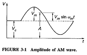
Voltage representation of AM wave: (Equation of double sideband- full carrier)
From the diagram we can observe the following:
vm(t)=Em Sin wmt
where, vm(t) be the instantaneous value of the modulating signal.
Em be the maximum amplitude of the modulating signal.
wm be the angular frequency of the modulating signal.
vc(t)=Ec Sin wct
where, vc(t) be the instantaneous value of the carrier signal.
Ec be the maximum amplitude of the carrier signal.
wc be the angular frequency of the carrier signal.
Therefore for amplitude modulated signal,
VAM (t) = (Ec + Em Sin wmt ) Sin wct
VAM (t) = Ec Sin wct + Em Sin wmt Sin wct
VAM (t) = EcSin wct +mEc Sin wmt Sin wct [ since m=Em / Ec]
VAM (t) = Ec {Sin wct +m Sin wmt Sin wct}
VAM (t) = Ec {Sin wct +m/2{Cos (wc-wm)t – Cos (wc+wm)t }}
[since SinASinB=1/2(Cos (A-B) – (Cos (A+B))]
VAM (t) = Ec {Sin 2∏fct +m/2{Cos 2∏(fc-fm)t – Cos 2∏(fc+fm)t }}
VAM (t) = Ec Sin 2∏fct – mEc /2{Cos 2∏(fc+fm)t – Cos 2∏(fc-fm)t }}
- Ec be the amplitude of the carrier signal.
- mEc/2 be the amplitude of the USB signal.
- mEc /2 be the amplitude of the LSB signal.
- fc be the frequency of the carrier signal.
- fc+fm be the frequency of the USB signal.
- fc-fm be the frequency of the LSB signal
Power distribution of AM wave:
Pc = Vrms2/ load resistor
i.e,. Pc = Vrms2/R
where, Vrms be the root mean square voltage.
Pc be the power of the carrier signal.
Vrms = Vm / √2 = Ec / √2
Pc = (Ec / √2)2 /R
Pc = Ec2 / 2R
PLSB = PUSB = (mEc /2)2 / 2R
PLSB = PUSB = m2Ec2 / 8R
PLSB = PUSB = (m2/4) * (Ec2 / 2R)
PLSB = PUSB = (m2/4) * Pc
Total power PT = Pc +PLSB +PUSB
PT =Pc+(m2/4) * Pc +(m2/4) * Pc
PT =Pc+2(m2/4) * Pc
PT = Pc+(m2/2) * Pc
PT =Pc( 1+m2/2)
Where, m is the modulation index.
PT is the total power.
Pc is the power of the carrier signal.