Boolean Multiplication and Division
Multiplication is more complicated than addition, being implemented by shifting as well as addition. Because of the partial products involved in most multiplication algorithms, more time and more circuit area is required to compute, allocate, and sum the partial products to obtain the multiplication result.
3.3.1. Multiplier Design
We herein discuss three versions of the multiplier design based on the pencil-and-paper algorithm for multiplication that we all learned in grade school, which operates on Boolean numbers, as follows:
          Multiplicand:   0010   # Stored in register r1
          Multiplier:   x 1101   # Stored in register r2
          --------------------
	  Partial Prod    0010   # No shift for LSB of Multiplier
             "      "    0000    # 1-bit shift of zeroes (can omit)
             "      "   0010     # 2-bit shift for bit 2 of Multiplier
             "      "  0010      # 3-bit shift for bit 3 of Multiplier
          --------------------   # Zero-fill the partial products and add
          PRODUCT      0011010   # Sum of all partial products -> r3
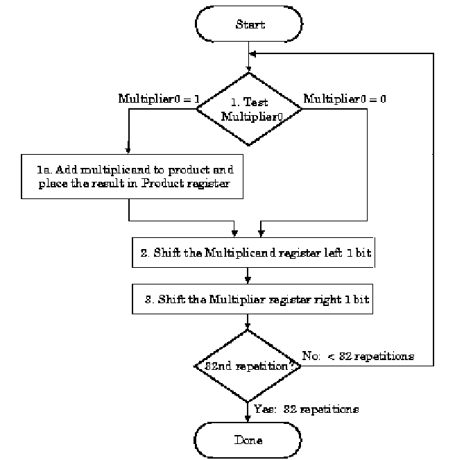
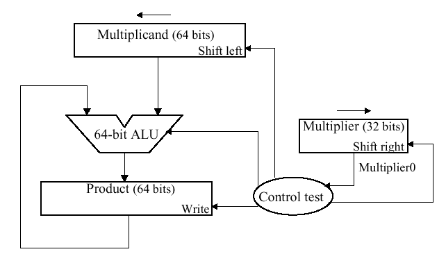
A flowchart of this algorithm, adapted for multiplication of 32-bit numbers, is shown in Figure 3.15, below, together with a schematic representation of a simple ALU circuit that implements this version of the algorithm. Here, the multiplier and the multiplicand are shifted relative to each other, which is more efficient than shifting the partial products alone.
(a)
(b)
Figure 3.15. Pencil-and-paper multiplication of 32-bit Boolean number representations: (a) algorithm, and (b) simple ALU circuitry – adapted from [Maf01].
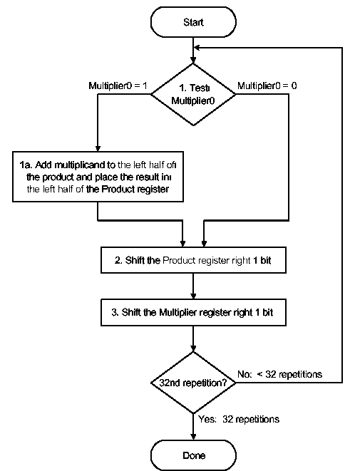
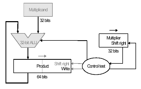
The second version of this algorithm is shown in Figure 3.16. Here, the product is shifted with respect to the multiplier, and the multiplicand is shifted after the product register has been shifted. A 64-bit register is used to store both the multiplicand and the product.
(a)
(b)
Figure 3.16. Second version of pencil-and-paper multiplication of 32-bit Boolean number representations: (a) algorithm, and (b) schematic diagram of ALU circuitry – adapted from [Maf01].
The final version puts results in the product register if and only if the least significant bit of the product produced on the previous iteration is one-valued. The product register only is shifted. This reduces by approximately 50 percent the amount of shifting that has to be done, which reduces time and hardware requirements. The algorithm and ALU schematic diagram is shown in Figure 3.17.
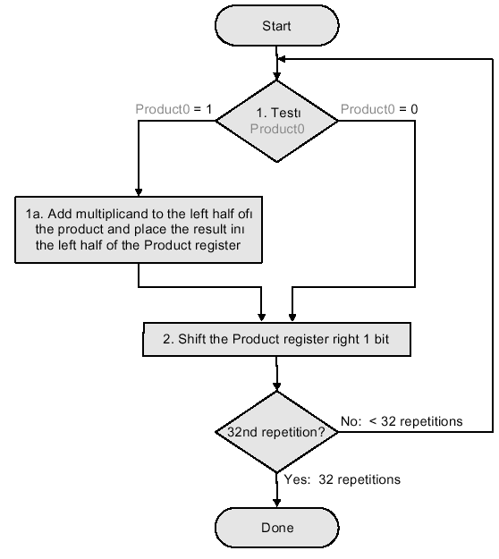
(a)
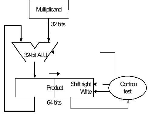
(b)
Figure 3.17. Third version of pencil-and-paper multiplication of 32-bit Boolean number representations: (a) algorithm, and (b) schematic diagram of ALU circuitry – adapted from [Maf01].
Thus, we have the following shift-and-add scheme for multiplication:
The preceding algorithms and circuitry does not hold for signed multiplication, since the bits of the multiplier no longer correspond to shifts of the multiplicand. The following example is illustrative:
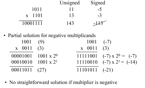
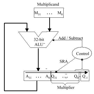
A solution to this problem is Booth’s Algorithm, whose flowchart and corresponding schematic hardware diagram are shown in Figure 3.18. Here, the examination of the multiplier is performed with lookahead toward the next bit. Depending on the bit configuration, the multiplicand is positively or negatively signed, and the multiplier is shifted or unshifted.
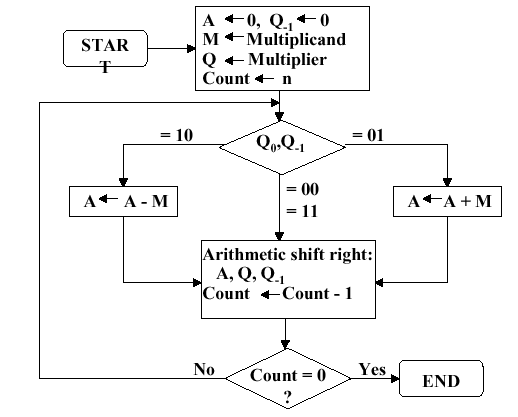
(a)
(b)
Figure 3.18. Booth’s procedure for multiplication of 32-bit Boolean number representations: (a) algorithm, and (b) schematic diagram of ALU circuitry – adapted from [Maf01].
Observe that Booth’s algorithm requires only the addition of a subtraction step and the comparison operations for the two-bit codes, versus the one-bit comparison in the preceding three algorithms. An example of Booth’s algorithm follows:
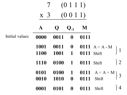
Here N = 4 iterations of the loop are required to produce a product from two N = 4 digit operands. Four shifts and two subtractions are required. From the analysis of the algorithm shown in Figure 3.18a, it is easily seen that the maximum work for multiplying two N-bit numbers is given by O(N) shift and addition operations. From this, the worst-case computation time can be computed given CPI for the shift and addition instructions, as well as cycle time of the ALU.
3.3.2. Design of Arithmetic Division Hardware
Division is a similar operation to multiplication, especially when implemented using a procedure similar to the algorithm shown in Figure 3.18a. For example, consider the pencil-and-paper method for dividing the byte 10010011 by the nybble 1011:
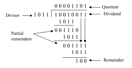
The governing equation is as follows:
Dividend = Quotient · Divisor + Remainder .
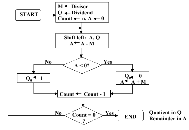
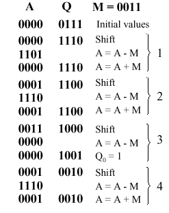
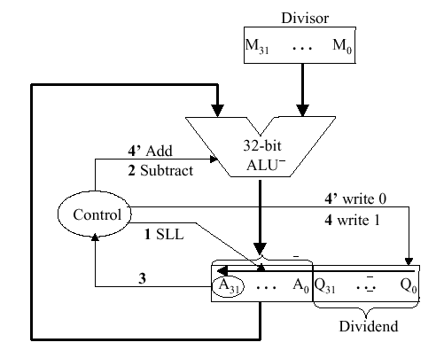
3.3.2.1. Unsigned Division. The unsigned division algorithm that is similar to Booth’s algorithm is shown in Figure 3.19a, with an example shown in Figure 3.19b. The ALU schematic diagram in given in Figure 3.19c. The analysis of the algorithm and circuit is very similar to the preceding discussion of Booth’s algorithm.
(a)
(b)
(c)
Figure 3.19. Division of 32-bit Boolean number representations: (a) algorithm, (b) example using division of the unsigned integer 7 by the unsigned integer 3, and (c) schematic diagram of ALU circuitry – adapted from [Maf01].
3.3.2.2. Signed Divisiion. With signed division, we negate the quotient if the signs of the divisor and dividend disagree. The remainder and the divident must have the same signs. The governing equation is as follows:
Remainder = Divident – (Quotient · Divisor) ,
and the following four cases apply:
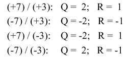
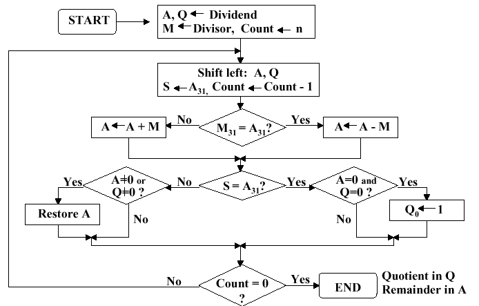
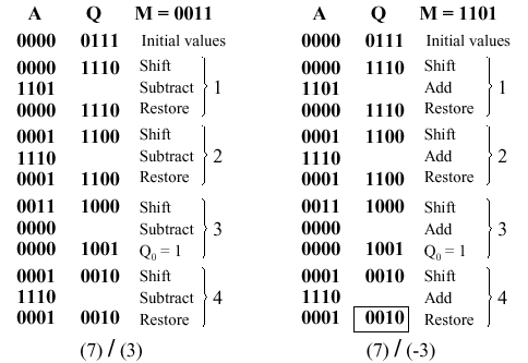
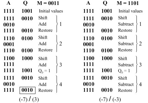
We present the preceding division algorithm, revised for signed numbers, as shown in Figure 3.20a. Four examples, corresponding to each of the four preceding sign permutations, are given in Figure 3.20b and 3.20c.
(a)
(b)
(c)
Figure 3.20. Division of 32-bit Boolean number representations: (a) algorithm, and (b,c) examples using division of +7 or -7 by the integer +3 or -3; adapted from [Maf01].
3.3.2.3. Divisiion in MIPS. MIPS supports multiplication and division using existing hardware, primarily the ALU and shifter. MIPS needs one extra hardware component – a 64-bit register able to support sll and sra instructions. The upper (high) 32 bits of the register contains the remainder resulting from division. This is moved into a register in the MIPS register stack (e.g., $t0) by the mfhi command. The lower 32 bits of the 64-bit register contains the quotient resulting from division. This is moved into a register in the MIPS register stack by the mflo command.
In MIPS assembly language code, signed division is supported by the div instruction and unsigned division, by the divu instruction. MIPS hardware does not check for division by zero. Thus, divide-by-zero exception must be detected and handled in system software. A similar comment holds for overflow or underflow resulting from division.
Figure 3.21 illustrates the MIPS ALU that supports integer arithmetic operations (+,-,x,/).
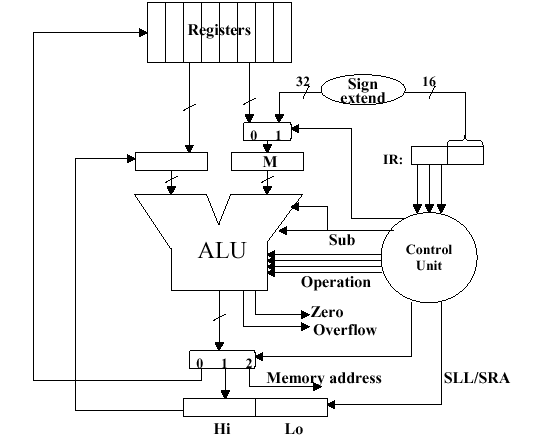
Figure 3.21. MIPS ALU supporting the integer arithmetic operations (+,-,x,/), adapted from [Maf01].

