
16 PSK
16-PHASE SHIFT KEYING (16-PSK):
- Angle modulated with constant amplitude digital modulation.
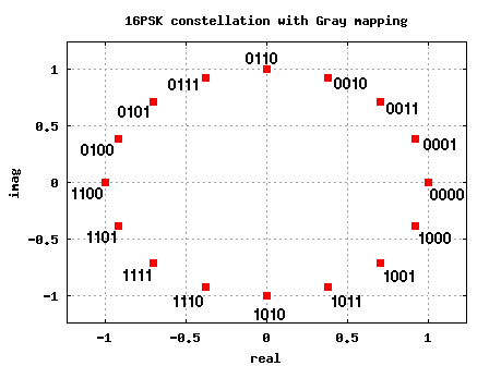
- 4 bits encoded forming and producing 16 different outputa are possible.
- N = 4, M = 2N = 24 = 16
Therefore 16 output phases will be produced
- Each channel bit rate is fb/4.
- The input bit is serially inputted and outputted simultanously as I,I’,Q,Q’ which are parallel to each other.
- I,Q determines the parity whereas I’,Q’ determines the magnitude (logic= 0.821V, logic 0= 0.22V).
- Two polarities and magnitudes are possible at 2 to 4 level convertor(±0.821 , ±0.22V).
- The output of I-product modulator, ±0.821 sin wct, ±0.22 sin wc
- The output of Q-product modulator, ±0.821 sin wct, ±0.22 sin wc
- The linear summer produces 16 output conditions.
Algorithm:
- I and Q represent the polarity.
- Logic 1 = +ve
- Logic 0 = -ve
- I’ and Q’ represent the magnitude.
- Logic 1 = 0.821V
- Logic 0 = 0.22V
-
I I’ output 0 0 -0.22V 0 1 -0.821V 1 0 +0.22V 1 1 +0.821V Q Q’ output 0 0 -0.22V 0 1 -0.821V 1 0 +0.22V 1 1 +0.821V Truth table:
I I’ Q Q’ 0 0 0 0 -0.22 sin wct – 0.22 cos wct 0 0 0 1 -0.22 sin wct – 0.821 cos wct 0 0 1 0 -0.22 sin wct + 0.22 cos wct 0 0 1 1 -0.22 sin wct + 0.821 cos wct 0 1 0 0 -0.821 sin wct – 0.22 cos wct 0 1 0 1 -0.821 sin wct – 0.821 cos wct 0 1 1 0 -0.821 sin wct + 0.22 cos wct 0 1 1 1 -0.821 sin wct + 0.821 cos wct 1 0 0 0 +0.22 sin wct – 0.22 cos wct 1 0 0 1 +0.22 sin wct – 0.821 cos wct 1 0 1 0 +0.22 sin wct + 0.22 cos wct 1 0 1 1 +0.22 sin wct + 0.821 cos wct 1 1 0 0 +0.821 sin wct – 0.22 cos wct 1 1 0 1 +0.821 sin wct – 0.821 cos wct 1 1 1 0 +0.821 sin wct + 0.22 cos wct 1 1 1 1 +0.821 sin wct + 0.821 cos wct 16-PSK receiver:
- The power splitter directs to the input 16-psk signal to I,Q channel product detectors and carrier recovery circuit.
- The incoming 16-PSK signal is mixed with the recovered carrier in the I product detector and quadrature carrier in Q product detector.
- The output of product detector(4 level PAM) is given to 4 to 2 level ADC’s.
- The output of ADC’s are Q,Q’ bits and I,I’ bits .
- The parallel to serial logic circuit gives Q,I data stream bit.
