
QPSK
Quadrature phase-shift keying (QPSK)

Constellation diagram for QPSK with Gray coding. Each adjacent symbol only differs by one bit.
Sometimes this is known as quadriphase PSK, 4-PSK, or 4-QAM. (Although the root concepts of QPSK and 4-QAM are different, the resulting modulated radio waves are exactly the same.) QPSK uses four points on the constellation diagram, equispaced around a circle. With four phases, QPSK can encode two bits per symbol, shown in the diagram with Gray coding to minimize the bit error rate (BER) — sometimes misperceived as twice the BER of BPSK.
The mathematical analysis shows that QPSK can be used either to double the data rate compared with a BPSK system while maintaining the same bandwidth of the signal, or tomaintain the data-rate of BPSK but halving the bandwidth needed. In this latter case, the BER of QPSK is exactly the same as the BER of BPSK – and deciding differently is a common confusion when considering or describing QPSK. The transmitted carrier can undergo numbers of phase changes.
Given that radio communication channels are allocated by agencies such as the Federal Communication Commission giving a prescribed (maximum) bandwidth, the advantage of QPSK over BPSK becomes evident: QPSK transmits twice the data rate in a given bandwidth compared to BPSK – at the same BER. The engineering penalty that is paid is that QPSK transmitters and receivers are more complicated than the ones for BPSK. However, with modern electronics technology, the penalty in cost is very moderate.
As with BPSK, there are phase ambiguity problems at the receiving end, and differentially encoded QPSK is often used in practice.
Implementation
The implementation of QPSK is more general than that of BPSK and also indicates the implementation of higher-order PSK. Writing the symbols in the constellation diagram in terms of the sine and cosine waves used to transmit them:

This yields the four phases π/4, 3π/4, 5π/4 and 7π/4 as needed.
This results in a two-dimensional signal space with unit basis functions

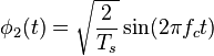
The first basis function is used as the in-phase component of the signal and the second as the quadrature component of the signal.
Hence, the signal constellation consists of the signal-space 4 points
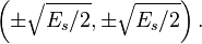
The factors of 1/2 indicate that the total power is split equally between the two carriers.
Comparing these basis functions with that for BPSK shows clearly how QPSK can be viewed as two independent BPSK signals. Note that the signal-space points for BPSK do not need to split the symbol (bit) energy over the two carriers in the scheme shown in the BPSK constellation diagram.
QPSK systems can be implemented in a number of ways. An illustration of the major components of the transmitter and receiver structure are shown below.
![]()
Conceptual transmitter structure for QPSK. The binary data stream is split into the in-phase and quadrature-phase components. These are then separately modulated onto two orthogonal basis functions. In this implementation, two sinusoids are used. Afterwards, the two signals are superimposed, and the resulting signal is the QPSK signal. Note the use of polar non-return-to-zero encoding. These encoders can be placed before for binary data source, but have been placed after to illustrate the conceptual difference between digital and analog signals involved with digital modulation.
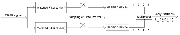
Receiver structure for QPSK. The matched filters can be replaced with correlators. Each detection device uses a reference threshold value to determine whether a 1 or 0 is detected.